
Most of you will have noticed, it's a difficult task to change something at the pit lane, so that the pit lane/track separation and joining still works correctly. So did I, and that is why I spent some time studying the basics. Some of the results have already found their way into the TE (Track Editor). Some things are still to be discovered.
I haven't (yet) stretched the subject to its limits. I rather tried to understand
why the original pit lanes work and why some others do not. I am sure there is still
room for experiments. Most of the facts show up in this note, but to fully understand
the subject, I suggest you study the pit lanes of original GP2 tracks. Jerez and
Estoril are good examples. You will also notice (once more) that the GP2-graphic-engine
is very tolerant, and sometimes it shows bizarre effects, when trying to sort track/pit
lane-layout errors.
The explanations are based on TE version 1.7.3 unless stated.
In the following picture you see the very basic of a pit lane. The screenshots are made with TE 1.7.3 of the original Jerez-track. The figures are the sector numbers of track and pit lane. In the first picture you see the track. Picture 2 shows the pit lane, and picture 3 both of them.

As you may see, the track and the pit lane are separated things. They need to get attached to each other in a certain way. The keys are the two cmds 0x86(134) and 0x87(135). The pit lane is connected to the track at the two track sectors including the two mentioned cmds.

In the next chapters I explain how the entry, the pit
lane itsself with the parking-zone and the exit works.
After this study of the basics we look at the pit lane as
a whole, how it has to fit in. Here we especially have to take care to length,
shape and heights of the pit lane.
At the end of the file you also find a glossary with explanations
of a terms used in this tutorial.
If there are errors or missing things in the tutorial, or if simple things are described
too complicated, please notify me. Any suggestions etc. are welcome ...
Overview
As we already concluded the pit lane and the tracklane are separated things which have to be connected in a certain way.
It all starts with the cmd 0x86(134) in any track-sector, preferably somewhere
toward the end of the track. At the beginning of the track-sector, which includes
the cmd 0x86(134), the sector 0 of the pit lane (p0) is connected, along the leftborder
of the tracklane for left-side pits, along the right border of the tracklane for
right-side pits.
For determining the side where the pit lane gets connected, you have to go to the
track-config-section in the track-tree of the TE. There you have the track-sections,
and in there the track-unknown-2-number. If you translate this number into a binary
number you got a lot of 0s and 1s, all in all16 (16 bits).
Example; We have for
Interlagos: 8074: 0001 1111 1000 1010
Silverstone: 8064: 0001 1111 1000 0000
See the difference ? Interlagos has its pits on the left side, Silverstone on the
right side! So, if the last block of four bits reads: 1010, you have the pits on
the left side. That means the pit lane starts and leaves through the left fence.
The parking-fields are also on the left side of the pit lane (you just have to adjust
the verge-value, set the floor texture, adjust the markings, the pit-building and
the pit-crew). At the exit the pit lane joins the track again through the left fence
and ends along the left border of the track. Even the sequence of the members within
the pitcrews changed, but they are still on their original side.
If you are not used to the bit-stuff you can just ADD 10 to the track-unknown-2-number,
if you want to switch from the right to the left-side, or SUBTRACT 10, if you want
to switch from the left to the right-side. Beware of doing this twice, there could
be bizarre effects!
Summary:
When the Pits are on the Right - ADD 10 - To put them on the Left
When the Pits are on the Left - SUBTRACT 10 - To put them on the Right
In the mentioned pit lane sector 0, there is always a cmd 0x9b(155). This cmd
MUST BE THERE - else GP2.exe crashes when loading the track. The argument of the
cmd 0x9b(155) is the offset into the pit lane sector to where the VISIBLE pit lane
begins (where the solid yellow lines start). Therefore, if you have a value of (9),
the pit lane is not visible over the first 9 unit lengths. It is actually there nevertheless,
but cannot be seen. Most of the original tracks have a value of 4, other values are
1-9. See also the sketch entry.jpg later in this tutorial.
The dotted yellow lines that you notice at the beginning of the pit lane are implemented
separately with cmd 0x8a(138) (see cmdlib for the details here).
The distance between the point where the cc-car reacts to enter the pits and the
visible-pit lane beginning appear to be stored in the GP2.exe. This reaction-offset
differs from slot to slot. You may check this out yourself by renaming the original
tracks and watch what happens when cc-cars try to enter the pits. After making
a backup of the whole circuits subdirectory, rename f1ct08.dat to f1ct01.dat,
start a quickrace and look what happens when a cc-car attempts to enter the pits
(I'll leave it to your imagination of how to encourage them to enter the pits:).
First you may want to try running the Silverstone track in the Interlagos slot. Then
look at what happens when Interlagos is in slot8. Try putting Interlagos in slot
6 (Normally Montreal which also has the pits on the left).
So it is important where you place your tracks. Sometimes it can be OK sometimes
not, but take care! It makes a difference whether you insert your track instead of
e.g. interlagos or instead of silverstone. These facts were brought to our attention
by 'Knuckles' <brett_knuchel@geocities.com>.
This subject is covered in more detail on the webpage of Armin Krausse: http://www.geocities.com/MotorCity/Speedway/7479/exchange.htm.
We have connected the two lanes and now we are going to separate them. The critical part is, where the pit lane goes THROUGH the fence of the track. We have to somehow cut a passage in the track-fence and connect the two ends of the divided track-fence to the two fences of the pit lane. To do this, we first have to layout the two lanes very carefully so the appropriate sector-ends match as precise as possible. Three cmds are important now. 0xa1(161) and 0xa2(162) in two different track sectors and 0x9f(159) in the pit lane. The cmds 0xa1(161) and 0xa2(162) mark the sectors where the fences of the track and the pit lane get connected. Cmd 0x9f(159) marks the first pit lane-sector with its own fences, it is here that the pit-fences get connected to the track-fences.
Please have a look at the sketch in entry.jpg.

Here we see a sequence within a track like e.g. Jerez with the pits on the left side
of the track. Track-sector-A includes cmd 0x86(134) to connect the pit lane. Track-sector-C
includes cmd 0xa2(162) {join left pit lane-fence}. This cmd means something like:
connect the beginning of my left fence to the beginning of the left fence of the
pit lane sector with the cmd 0x9f(159). Then we have track-sector-D with the cmd
0xa1(161) {join right pit lane-fence}, which reads: connect the beginning of my left
fence to the beginning of the right fence of the pit lane-sector with cmd 0x9f(159).
The last thing we have to do yet, is to remove the texture of the fence of sector
C. We do this by checking the "remove TEXTURE" of the left-fence in the
fences-checkbox-section in the track-change-dialog-box.
We can say now: the pit lane leaves the track-lane through the left fence of track-sector-C.
That's the whole story, as far as I know. Although you still will have to deal with
the scenery and objects etc.
If the pit lane leaves on the right side, the principle is the same. Only the cmds
0xa1 and 0xa2 would be reversed, and the pit lane would leave through the RIGHT fence
of track-sector-C. 0xa1 always connects to the right-fence of the pit lane-sector
with cmd 0x9f(159), 0xa2(162) always connects to the left fence of the pit lane-sector
with cmd 0x9f(159).
Summary:
cmd 0xa1 {join right pit lane-fence}
cmd 0xa2 {join left pit lane-fence}
Sequence 0xa2 followed by 0xa1, if you have pits to the left.
Sequence 0xa1 followed by 0xa2, if you have pits to the right.
We mentioned earlier, that the pit lane and the track are two separated graphical
objects, defined by their own tables. That means that the GP2-engine normally draws
the track only, when you are on the track. If you are approaching the pit-entry,
the GP2-engine also draws the track, and the pit lane only until where it goes through
the fence of the track. Beyond that point, there is NOTHING, emptyness, normally.
To prevent that, there is the cmd 0xd3(211). It has two arguments, the first is the
offset into the track-sector where it resides, and the second is the length of the
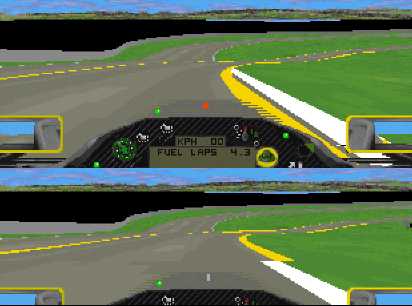
VIEW into the pit lane. The following screenshots show the view from the very same
point at the pit entry in Imola. The car is positioned just in front of the point
where the pit lane goes through the fence of the track.
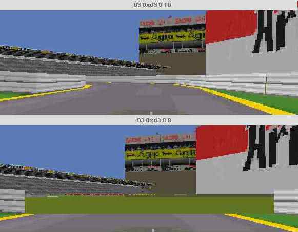
In the upper screenshot the 2nd argument of 0xd3(211) is set to 10. In the lower
screenshot the second argument of 0xd3(211) is set to 0.
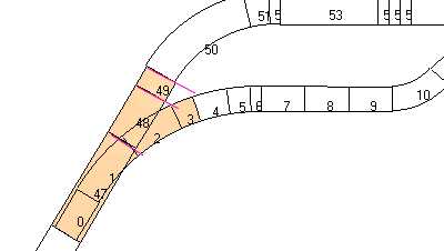
Now lets have a look at a sketch.
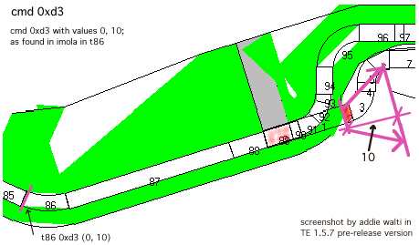
In Imola we find the 0xd3(211) cmd in t86. The first argument is 0, which means the
EXTENDED view starts right on the beginning of track sector 85. The pink arrows and
lines mark the range of the extended view into the pit lane.
Of course there is also a view into the pit lane on the other side, the pit-exit.
There you find the cmd 0xd5(213). It works in a similar way ...
You especially have to take care on this cmd if you are moving your pit lane backward,
or if you change the layout of the pit-entry.
Thanks go to John Verheijen (jw.verheijen@wxs.nl) who directed my focus on 0xd3(211).
Sometimes we have all straight pit lanes as can be seen in Monza. Actually in Monza it is possible to see through the whole pit lane. Or you the whole pit lane from one end, entry or exit, as can be seen in the authors track Bern-Grauholz 1999. In the later you see the whole pit lane when looking into the exit.
This special view is enabled by the cmds 0xd4 (212) and 0xd6 (214). They both have to be there. They somehow do define an section on the track where the whole pit lane is visible.
In Monza the 0xd4 (212) is placed before the entry and cmd 0xd6 (214) after the exit. This works because the pit lane is all straight. In Bern-Grauholz 1999 it didnt work, because the entry of the pit lane is a corner.
We are now talking about the section of the pit lane, that starts with the pit lane-sector including the cmd 0x9f and ends before the pit lane-sector including cmd 0xa0. The pit lane-sectors with their own fences.
In the track-change-dialogbox you see a checkbox-section labelled "Pit Lane". These checkboxes have to be checked through the pit lane in a certain way. The pit lane-sector with cmd 0x9f is ALWAYS the first with a checked 0x1checkbox. All the following pit lane sectors until about where the cmd 0x97 is (speed-limiter-off), also have this checkbox checked. The pit lane-sector with the cmd 0x96 (speed-limiter-on), is about the first pit lane-sector with a checked 0x2 checkbox. All the following pit lane sectors have this checked too, until the sector with the cmd 0xa0. This sector is ALWAYS the first with unchecked 0x2 checkbox. The start of the 0x1 row and the end of the0x2 row are given, but because the actual function of these checkboxes are not yet clear, we cannot say when the 0x1 row has to end and when the0x2 row has to start. You may want to apply the well-known trial-and-error-method. You may also want to have a look at an original GP2 track, to see how they look there.
Somewhere in the middle of the pit lane is a sector that starts the parking-zone,
where you get new tyres and the visor cleaned. It is the sector that includes the
cmd 0x88 or 0x89. The parking-zone has a length of 48 and the verge-value on the
appropriate side is always 82 in the original GP2 tracks, but I guess these values
are not carved in stone. You can cover more than one sector, e.g. with different
angles (see Monaco). The sectors that contain the parking-zone always have checked
the two checkboxes of the Pit lane-checkbox-section in the track-change-dialogbox.
There is no room for experiments here. If one of the boxes is unchecked, the
parkfield doesn't work anymore, and you immediately get thrown out of the pit lane
(actually the fastest way I know to leave the pits:)).
At this sector(s) you also need to remove the texture of the fence(s) (check the
remove-texture checkbox in the fences-checkbox-section in the track-change-dialogbox)
on the parkfield-side, so the pitbuilding-texture is not covered up by the fence
texture.
The parkfield texture is controlled by the cmd 0xbc and most of the time is found
in the same pit lane-sector, where you will also find the cmd 0x88or 0x89. After
opening the mentioned cmd 0xbc, you can change the location and the rotation. The
location changes from right floor to left floor (code8 to 9) or vice versa. To make
a perfect job, you also need to rotate the texture by + or -180 degrees (+ or -32
in the properties box). If working with the texture-chooser-dialog box, be sure to
verify whether the TE really saved your changes, because not every version does (TE
1.5.7 does). If the texture-chooser does not work properly, you may change it in
the properties-box at the bottom of the TE window.
The other markings, the white and the yellow lines are controlled by the cmds 0x8a
and 0x8b that you find in every pit lane. You basically have to change the sign of
the values in the arguments, Horizontal Movement and Angle of line (these and other
possibilities of the cmds 0x8a and 0x8b are also described in other tutorials).
Last but not least you may also want to switch the side of the pitcrew. To do this,
go in the Object Definitions in the Track Tree, and look for the line labelled with
Pit Crew. Here you just have to change the sign of the value of the Y-argument (many
thanks to Knuckles!).
The mentioned cmds 0x88 (left-side-pit lane) and 0x89 (right-side-pit lane) have
two arguments, and the values of them are always 0 and 16. Up to now its not clear
what the difference is between the two cmds and what the meaning is of the arguments.
As far as I noticed, both cmds work the same way?! However; there HAS to be one of
them there. Removing them will cause the worst crash when trying to load the track
in GP2 afterwards (it even hanged my virtual PC and (with it) the Macintosh!!).
Most of the time there is also an object-cmd which defines the pit-building. To
switch its side you change the sign of the value in the Y-argument of the object
definition and you change the X-angle from 0 to 32768 or vice versa (as far as I
know, but actually I donít know much about objects and their definition).
In Monaco the pit-building texture is mapped on one of the ribbons ! Here switching
the side of the pitbuilding would be a bitmore difficult, look out for a scenery-tutorial
on this.
As John Verheijen wrote <jw.verheijen@wxs.nl > it:
About editing the pit building I can say the following.
Y = Move the pit building to the left or the right.
Angle x = Turn the pit building at the start and end to the left or right.
Angle Y = Move the pit building at the start of end down or up. This depends on the
angle of the start/finish straight.
Within the pit lane, you also have the two speed-limiter cmds 0x96 (speed-limiter
on) and 0x97 (speed limiter off). They HAVE to be there. If you remove one off them,
the pits-routine doesn't work anymore. You can still drive through the pit lane,
quasi-alternative tracklane, but you wont get any more fresh tyres and clean visor.
Overview
At the exit of the pits, the pit-lane has to go through the fences of the track again. It is basically the same thing as with the entry.
Please look at the sketch exit.jpg.

Here we have the pits on the left side. The pit lane goes through the left fence
of track-sector-B.
Track-sector-B also includes the cmd 0xa3 {join right pit lane-fence} which reads:
connect the beginning of my left fence to the beginning of the right fence of the
pit lane-sector with cmd 0xa0. Track-sector-C includes the cmd 0xa4 {join left pit
lane-fence} which reads: connect the beginning of my left fence to the beginning
of the left fence of the pit lane-sector with cmd 0xa0.
The pit lane-sector with the cmd 0xa0 is the first pit lane sector WITHOUT its own
fences. The rest of the pit lane has to lead towards the track-sector with the cmd
0x87.
We also have to remove the texture of the left fence of sector B, to do a proper
job. But its the same here: no need to check the other (the bridge-) checkbox (see
pit lane entry).
Summary:
cmd 0xa3 {join right pit lane-fence}
cmd 0xa4 {join left pit lane-fence}
Sequence 0xa3 followed by 0xa4, if you have pits to the left.
Sequence 0xa4 followed by 0xa3 if you have pits to the right.
On the pit lane exit the view-into-pit lane works similar to the pit lane-entry. Here you take the cmd 0xd5(213) and apply it the same way you did apply the 0xd3(211) on the pit lane-entry.
The end of the last pit lane-sector gets connected to the beginning of the track-sector including the cmd 0x87.
Now we want to have a closer look at how to fit in a whole pit lane. As we have seen at the top of this document we have two key-points. The two key-points are the track sectors including the cmd 0x86 (134) and 0x87 (135). Our pit lane has to fit in as perfect as it gets between these two points. This means, shape and heights have to match.
Shape
Before getting together the perfect shape of the pit lane we have to ensure, the shape of the track in terms of matching of the ends is perfect. Perfect matching of the ends look like in the following screenshot. The screenshot is from the original Jerez track (f1ct14.dat). At the left you see the matching of the two ends of the track (start/finish; s/f) with a certain overlap (a). There IS an overlap of 1 length unit in the game (i checked that by the help of mapping textures on the road). To get an idea of these overshots, have a look at the original tracks and keep in mind that they DO work.
At 2nd the angle of the two ends have to match as precise as it gets. These two
points are neccessary to have a chance to get together a working shape of the pit
lane without too much pain.
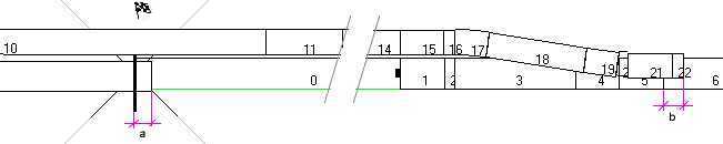
a: overshot at track-beginning
b: overshot at end of pit-lane
As you already have seen, the TE attaches the beginning of the first sector of the pit lane to the beginning of the track sector including the cmd 0x86 (134). This corresponds to what can be seen in the game. In order to really see it, you may want to set the value of the cmd 0x9b (155) to 0 for this period of work.
Now we can have a look at the attachement of the end of the pit lane. As we can see in the example above (and in every working track) there is also an overlap similar to the one at s/f
If the track doesnt load, maybe also the overlap at the pit lane exit is too big. If it is too small the track will load, but there will show up other nasty things as we will see next.
If the overlap is too small, the pit lane is simply to short and there will show up a gap in the pit lane road somewhere:
The gap in this example showed up at a pit lane entry. But it can show up also at the exit or probably at entry and exit. It depends on the placing of the fence-attachement cmds (as explained in the Pit Lane Entry and Pit Lane Exit chapters). The gap in the above screenshot could be fixed be increasing the length of the very last pit lane sector by one (increasing by another one hanged gp2.exe when loading the track).
My rule is: keep the overlap too short at the beginning, then increase until the
track hangs, then step back by one.
The following example features a gap at the exit. It could be fixed by increasing
the length by 2.

You do not necessarily have to increase the LAST pit lane-sector. In fact, you can
increase the length of ANY pit lane-sector.
In one of the last pit lane-sectors there is always also a cmd 0x9e(158).
It has a single argument that is almost equal, but always less the length
of the rest of the pit lane from there, see also the sketch exit.jpg above. It defines
the length of the visible rest of the pit lane (thanks Knuckles!). But opposite to
the pit lane-entry the cc-cars follow also the invisible part of the pit lane (keyboarder
only: have you ever left the adelaide pits in a hurry?)
This is how Knuckles <brett_knuchel@geocities.com> wrote it:
"In particular you design the pit lane ending to how you want the Computer Cars
to leave. It cannot be controlled by the 0x9e cmd. The computer cars do not go onto
the racing line until the actual exit [actual end of last pit lane-sector]."
My experiments showed me, the value of a1 has to be at least smaller by 2. In the original tracks the values are smaller by 2 - 6.
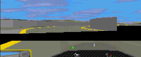
If the value is smaller by just 1, you will get a strange gfx bug at the pit lane end. It will look about this:

(maybe its not really clear on this screen shot; but you will reckognize it when you see it in your track!)
If the value equals the length of the rest of the pit lane, the track will hang gp2.exe when loading it.
Last but not least, as Martin Keizer found, if the value is greater than the length of the rest of the pit lane, the rest of the pit lane won't be visible at all (and sometimes the track hangs gp2.exe).
We concluded the pit lane has to fit in as perfect as it gets between the two key points on the track were the cmds 0x86(134) and 0x87 (135) sit. Unfortunately the TE does not show the geometry 100% perfect all the time, so we have to improvise with angles and lengths from time to time.
I'm afraid i cant tell you some rules here, but we can have a look at some indicators. First we have to keep in mind how the pit lane gets attached at the beginning. See the following image. You see a track / pit lane attachement in TE 1.7.3. You see the discrepancy between the showing up in the TE and the showing up in the game.

Beside the shift at the beginning, we have another shift at s/f. In the track in the following examples there we have a slight shift to the right (as is indicated with the red lines). So we have to improvise a bit at the shape of the pit lane. Our experiments will be within the following ones (cmd 0x87 sits in t4):

And when looking at the game we will notice gaps in the pit lane as mentioned earlier, and things like can be seen in the following shots:
Here you see mismatches of the white and the yello borderlines. If the geometry is perfect, both lines match. The same problems we have to face when setting up the fences as described in the chapters Pit Lane Entry and Pit Lane Exit. As I said there is no rule. It remains trial and error. Once more a good thing is having a look at the original tracks in the TE, keeping in mind they DO work, and match almost perfect.
Another chapter in editing pit lanes is the height question. You all know about the heights in the track sectors and you know about how to deal with them. But doing the same in the pit lane shows bizzare results. Whats going on ?
Remember how the shape of the pit lane has to fit ? Its the same with the heights ! And they basically work the same as with the track heights, but the circumstances are different. For making everything clear lets have a look at the following sketches:
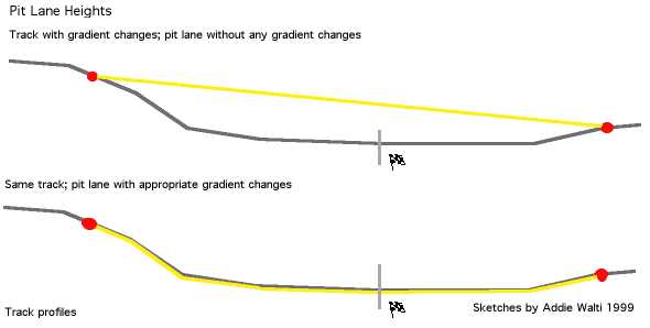
In grey we see the profile of a track with bad gradients at the end. I know its overshot
but its good for our example. The yellow line is the profile of the pit lane. The
red dots mark the attachement points of the pit lane.
Now the first example features a pit lane without any gradient changes. All heights are set to zero. The 2nd example shows a pit lane with perfect matching heights. Dave "SNQQPY.DOG": "In order to fix the pit exit at IA A1-Ring. I found that I had to ensure that the top of the Pit lane exit was almost equal to the Height of the track at that point. Just after the last turn of the track, the track goes down hill. The pit exit has to exactly match that gradient at its exit, to stop the exit either coming up through the track or suddenly falling off the pits because you are too high. If either is wrong you have a messy Pit-Exit."
Now lets cut out the pit lane and rotate it in order to get a zero-starting-gradient:
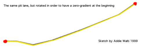
Although it looks easy, dealing with those heights is not exactly easy.
Here a possible way. In the following example we had some gradient changes in t47, t48 and t49. The rest of the track has no more gradient changes. Here i tried to get pit lane sectors with similar lengths. And as they had similar lengths, i inserted the same height-values, and it worked !
The basics of the pit lane heights were brought to me by Ando.
TE
Short name for track-editor.
Track-change-dialogbox
The dialogbox, where you change track-sectors or pit lane-sectors. It includes edit
fields for changing length, angles and stuff, and a lot of checkboxes.
Cmd
Abbreviation for command. For a summary of the commands see the Command Library
Track-tree-view
The track-tree-view is the tree-view in the window on the left side of the track
editor window. You can turn this window on and off with the appropriate button in
the toolbar.
Track-sector
A single piece of the track. A track-sector is defined by an entry in the track-data-table
AND an entry in the track-data-section in the track-tree-view. I use the abbreviation
t for track-sector. So t17 means track-sector 17.
Track section
General term. Means some track-sectors in a row, sometimes with a common property.
E.g. uphill track-section means some track-sectors where there is an uphill gradient.
Pit lane-sector
A single piece of the pit lane. A pit lane-sector is defined by an entry in the pit
lane-data-table AND an entry in the pit-data-section in the track-tree-view. I use
the abbreviation p for pit lane-sector. So p17 means pit lane-sector17.
Slot
The GP2.exe can handle 16 tracks. They always have to (have to?) be called f1ctXX.dat,
where XX means a number between 01 .. 16. These 16 possibilities I call slots. You
insert your track into one of these slots by giving your track-file a name f1ctXX.dat
and copy it into the circuits-Subdirectory.
Overview
Version 3.0
-rework +pit lane geometry chapter.
Version 2.4
-remove download facility, because there is now a general download facility at the
tutorial page
Version 2.3
-Translated to english by SNQQPY <snqqpy.dog@virgin.net> (thanks Dave!!)
-Included some hyperlinks to make it more usable
Version 2.2
-Tutorial now based on TE 1.5.7.
-Revision-history moved at the end of the file.
-With the release of TE 15.7 the addendum about the fences-bug and the insert-cmds-problem
became obsolete, so I removed it.
-The former addendum II got included in the chapter PIT LANE-ENTRY
-the chapter about left- or right pit lanes got integrated in the PIT LANE-ENTRYchapter
-revised chapter about pit lane-checkboxes.
-Extended chapter about connecting lanes again ! including resolving "gap-in-pit
lane"-problem. Plus hints by Martijn Keizer for possible resolving gfx-bugs
in pit lane exit.
-A few remarks to heights in pit lane
-slightly revised remarks concerning slot-specific code in the gp2.exe after discussing
it with Knuckles <brett_knuchel@geocities.com>.
-Removed the bridge-fences excursion because its detailed explained in "theguide
to track editing" of the same author.
-Extension of glossary by the term "slot"
-replaced the term "parameter" by the term "argument"in order
to assimilate this tutorial to the cmd-library.
-Applied some capitals in order to make the text more readable (thanks to martijn
keizer for the tip!)
-Little changes here and there.
Version 2.1
-Includes the cmd d3 and cmd 0xd5; see paragraph view into pit lane in chapter
PIT LANE-ENTRY. these cmds are especially important when movinga pit lane.
-The general entry-sketch now (quick&dirty) visualises the argument of the cmd
0x9b in p0 (pit lane sector 0), see chapter PIT LANE-ENTRY.
Version 2.01
-introduced some rudimentary version management.
-Changed link to additional informations of Armin Krausse in ADDENDUM II
-Last but not least correct spelling of Armins last name (sorry Armin!).
Version 2.
If you already know the first version of this tutorial, here a brief summary of the
revisions. The mentioned last secret, the changing of the side of the pitcrew, got
discovered (see chapter PIT LANE). On the other hand I noticed some new weird stuff.
The setting of the 0x1 and/or 0x2 checkboxes of the road-sign-flags-box of the pit
lane sectors are more extended, than I havedescribed in the first version. they have
to be checked almost all over the pit lane (see chapter PIT LANE). The cmd 0x9b is
also described now (see chapter PIT LANE-ENTRY), and it seems to exist some slot-specific
code in the gp2.exe (see ADDENDUM II). Then I extended the chapter PIT LANE with
some information about markings and textures.
Version 1
First version
Overview