by addie walti

Based on TE 1.7.x , if not otherwise declared.
index
Version 2.5b
by addie walti
Based on TE 1.7.x , if not otherwise declared.
index
FOREWORD
INTRODUCTION
OVERVIEW
TRACK CHANGE DIALOG
TRACK GEOMETRY
Track Width
Road Signs
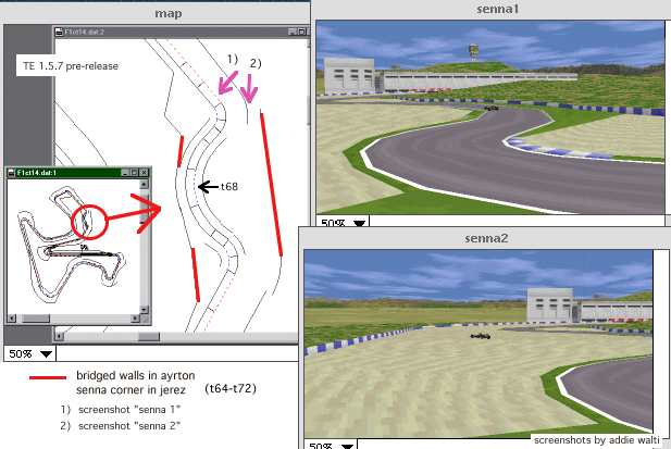
Bridged Fences
Kerbs
Verge Width
cc-line editing
USED ABBREVIATIONS
Revision History
You want to make your own track for GP2, and you see the TE (track editor) of Paul
Hoad and start immediately. But after a short while you realize its not easy going
because a GP2-track is a (very) complex object with different tables and other data.
And you have to do a lot of things until you can drive the first time on your own
track in GP2. Actually it is hard work and needs a lot of time (and nerves) to make
a new track. And the bad news is: nobody can change that. But we can try to provide
as much information as is available. These days there is a lot of knowledge around
about track editing and debugging, but unfortunately it is wide scattered. And there
are still secrets.
This is a try to make a summary of all knowledge how to deal with GP2 tracks in general
and the track editor of Paul Hoad in particular. I collected the knowhow at the beginning
out of any tutorial i could get my hands on, then i had to find out a lot of things
by myself. Over the last few months i also watched the track-editing-forum and collect
the posted know how. People that mainly started me off with or without knowing about
it: Paul, Ando, Ponk and of course Norman Surplus with the making of the original
tracks (very hard to beat, honest compliment!). These days i'm working together with
several people, they are named in the tutorial, where they got the most influence.
All mentioned tutorials are available from the tutorials-page of the track-editor
homepage.
This tutorial will get published in several revisions. It will grow. It needs a lot
of time to find out and verify all the info, and I am in the middle of it, and as
a working person I dont have all the time I needed. But I honestly would like to
help people starting off with track editing as fast and as good as I can. So watch
the version number on top of the file and the Revision History
on the bottom to find out if there is new info in the tutorial. And one day I will
change the title to "The Complete Guide To Track Editing", probably the
same day when GP4 will be out ...
Drop me a line if you like it. If there is no feedback, I might come to the conclusion
that there is no interest. And of course, if you have corrections, additions, (maybe
you would like to see a tutorial of yours included here) etc. please let me know
...
(and make frequently backups of your work, in a save place. I mean it!)
happy editing
addie@asit.ch
Track editing consists of several steps. The first step to edit will be the track
itself, the geometry or layout, the corners and straights and the gradient changes.
We also want to define kerbs and road signs. Along the track we have the verges,
where we can define gravel traps, grass or tarmac. We have the fences which are the
ultimate border for the cars. (As far as I know, nobody could really cross a fence
of a GP2-track up to now. Although there are rumours that it should be possible anyway.
But we are in for racing, arent we ?)
The track is defined by a lot of sectors that are stored in a table called track-data-table
(to be found in the "Track" and the "Tables"-menu). By doubleclicking
an entry of this table there shows up the track-change-dialog where you can define
all the parameters of a single track sector. A single track sector has a length ("Length"),
a constant curvature ("Angle") and a constant gradient change ("Height").
In the track change dialog you also can define the verge width at the end of the
sector, you can enable road signs and kerbs. There are also some more things there
that we examine later.
The track sectors also can be accessed in the track-tree. If you open the track-data,
you see the list of all the sectors of your track. You notice a sector can be opened
in the track-tree too ! (But you may not want to work in the track-tree AND the track-data-table
at the same time, because the TE seems to be not very stable here) If you open the
sector you see, that there are more or less commands belonging to the several sectors.
There exists a library of descriptions of all these track commands, collected and
formatted by the same author.
In the following picture we see the track-tree on the left and the track-data-table
and the track-view on the right.
(te.jpg; click to enlarge) 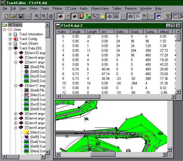
Another important subject is the pit lane. Basically the pit lane is defined similar
to the track, with one litte difference: while the two ends of a track are always
connected, the two ends of a pit lane are connected to the track somewhere. But this
is a story by itself, and it is in details described in another tutorial of the same
author ("the guide to pit lane editing").
Once we have the track and the pitlane we can say our track is basically working.
The next thing will be the scenery and the objects and the textures, because we not
just want a working track, but we want a NICE (and working) track. The scenery is
mostly defined with track- and pit lane commands. Details about dealing with the
scenery can be found in the scenery- tutorial of Martijn Keizer.
The objects are defined by object tables and placed by track- and pit lane commands.
You find a tutorial on objects by John Verheijen.
The textures are defined in JAM-files and placed with track- and pitlane commands.
Last but not least we have to make the CC-line. I suggest to wait with developping
the CC-line until the track is nearly finished. Because once the CC-line is made,
it is close to impossible to change something at the track-layout without loosing
the CC-line. And as developping a good CC-line means a dozen or more hours of hard
work, we dont want to loose it anymore. We just may want to replace it by a better
one. If you intend to make a completly new track layou, you may want to do a "CC
Line / Straighten CC-Line" first.
In general you may want to start track editing by having a closer look at existing
tracks. By making experiments with the several arguments in the track change dialog
you will more and more get a feeling for what is going on.
And you may want to make often backups of the track you are working on. It may happen that the TE cant load your track anymore, or in certain conditiones a certain function can mess your track completely and definitely up. then you probably will HAVE to go back to a backup. Most people of the track editing community experienced this (me included).
For your own track, you have to start with an existing track as base. Making a
new track from the scratch is not possible yet. Choosing the right base can be important.
Basically i would suggest to choose the track that comes closest to "your"
track.
First lets have a look at the track change dialog.
Here we can define the track- and also pit lane sectors. Most of all we can set up
the geometry and enable/disable features like kerbs and road signs.
As mentioned before we can call the track change dialog out of the track-data-table
or out of the track-tree. When we first concentrate on geometry, we may want to use
the table, because in the table we also find useful additional info on our track
sectors. If we do deal with features and commands, we may prefer the track-tree,
because THERE we have the commands.
After finishing the track we also may want to have a working pit lane. How to do
it is described in the pitlane tutorial of the same autor, so we do without it here.
Basically dealing with the pit lane is similar to dealing with the track. The difficulties
start when we want to connect it to the track.
A big chapter is the work on the scenery. With scenery we mean the space on the other
side of the fences. Basically we have some ribbons that can be formed to look like
hills or dips or flats or whatever.
(b8_bas2.jpg; click to enlarge) 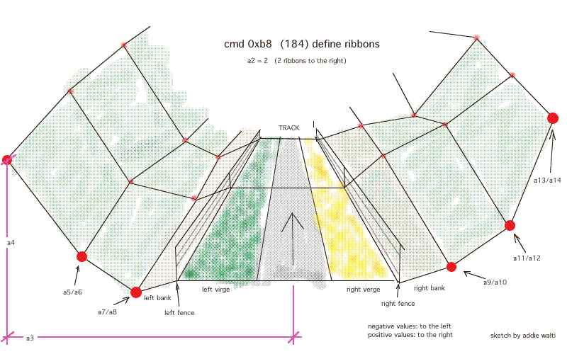
The scenery is most of all controlled by track commands. The details can be read
in the scenery-tutorial of Martijn Keizer. In the following picture we see a very
nice example of what can be done with scenery. It is a screenshot of the Sepadelft-track
of Martijn Keizer.
(dip1.jpg; click to enlarge) 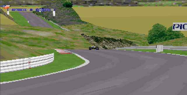
In this picture we also see, where the scenery ends, and maybe we get an idea of
how scenery works. Martijn worked with but one ribbon on each side, placed some objects
and mapped some textures in a very efficient way.
We now have defined a lot of areas, track, verges, fences, banks, ribbons, etc. As
already mentioned the next thing we want to do is mapping Textures
on them. Thats when they start looking good. To have an idea of what textures
are, you may want to go into the graphics-options-screen in the GP2.exe and disable
all textures and then have a look in the GP2.
Last but not least we want to spend some 15 or more hours by developping a good CC-Line. The CC-line is the driving line that will be followed
by the CC-cars and the steering help for keyboard drivers. So if there is no CC-line,
there will be no races against CC-cars (at least not very long ones) and no reasonable
keyboard driving on the track.
Overview
In this dialogbox you see some editfields and a load of checkboxes. With the editfields
in the boxes Length, Angle and Height you can control the geometry of the track sector.
Length is length, the angle and the height are a kind of curvature (german: krümmung).
More to these parameters in the chapter Track Geometry.
(dlgbox.jpg; click to enlarge) 
In the Verge section there are two fields for editing the verge wisth. The verge
is the space between the track and the fences along the track. Thats where we always
get lost in gravel traps or loose the frontwing when hoppling through the grass,
or sometimes when we are lucky, there is also tarmac and we can make a power turn
and rejoin the race again. With the two editfields we can control the distance between
the track and the fence. See the chapter Verge Width. by
Nic "Swervin' Irvin'" Prins later in this tutorial.
Next we have a section "Road Signs", see the chapter Road
Signs. later in this tutorial. The section "Fences" features the checkboxes
used to bridge fences. See chapter Bridged Fences later
in this tutorial. The checkboxes of the "Pit Lane" section are described
in the pitlane-tutorial, that you also find in the tutorials section of the track
editor homepage.
Next we have a Kerbs section, where you can choose whether you
want kerbs or not. See the Kerbs-Tutorial by Nic "Swervin' Irvin'" Prins
for how to deal with kerbs.
In the section "F1GP Codes & Unknows" you find some more checkboxes
that are not really known (thats why the section is called "Unknowns")
Last but not least you see two editfields RS (Road Signs) and KB (Kerbs). These two
fields are the container for all the checkboxes. If you check or uncheck a checkbox
you will notice one of these fields also changing, and vice versa. That means you
have the choice: you may either do it the hard way and edit the numbers or you may
do it the little less hard way and deal with the checkboxes.
Overview
In the track-change-dialog we saw, where we can control the track geometry parameters.
Now we all wonder about their meaning.
Length
Length is easy to understand. We only wonder about the UNIT. Looking at the original
tracks, the unit is somewhere between 4.80 (jerez) and 4.97 (silverstone), ever,
this can be determined by dividing the real length of the tracks (as given in the
GP2-manual!) by the number of length units of their GP2-pendants (but watch out in
adelaide!). Because Geoff Crammond is british, we have a look at the british length
system. After a short while we see that 16 feet (1 foot: 30.48cm, at least my english
dictionary says so) are 4.877m, bingo ! I guess this is obvious enough. Paul first
mentioned this fact somewhen in the forum, but doubted it later again. Now addie
says: 1 unit ALWAYS means 16 feet (about 4.877m).
Its a pity we have to deal with such a wide grid. Sometimes we wish to have a sector
length of say 2m or less, especially in corners, and when we would like to do a proper
job. But it is as it is, and its good if we know this BEFORE starting to plan the
exact layout of our dream track.
Angle
Now we turn to the tougher business, the Angle. The angle is hard to understand,
because it is NOT an angle value. I guess the mathematicians call this value CURVATURE
(german: krümmung). It is a value, saying HOW MUCH a line is bowed. The higher
the value, the tighter the curve. But when we want to know about the angle, we have
to look at the length of curved line, and multiply. Now we really have an angle (unit:
degrees; 360 degrees means full circle), in the track-change-dialog and in the track
data table this product (angle x length) is labelled ARC, so if we want to know the
angle of a curved sector, we do look in the arc-field in the track-change-dialog
or in the acr-column in the track-data-table.

(t_geom.jpg)
In this example we see a straight sector, then a curved, then again a straight sector.
We are talking about the curved sector here. In this sketch you see what is meant
by start- , endangle and arc-value of the track-change-dialog (the horizontal line
at the bottom is the base line, 0 degree).
Now we see the meaning of length and angle and we wonder how to translate the prefect
corners on the map of our dream track into GP2- track-sectors. Because the grid of
the length is that wide i guess we ever have to improvise, so probably the best way
to work, is to underlay the map in the TE and then developpe the track by trial and
error. We do underlay the map by generatin a bitmap, then calling the menu-function
File / Underlay Bitmap, then fine adjustment of the underlaying bitmap in the track-tree,
in the "Misc Config" section.
Height
After messing around with the Angle-value, we are equipped with knowledge about higher
mathematics and can turn to the real deal now: the Height value. Same here: Height
has nothing to do with height in real life. Height is again some kind of curvature,
but when multiplying this curvature with the length of the sector we do not get an
angle, but we get a gradient-change. The gradient gives you the amount of height-change
per length. E.g. if gradient is 10 and length is 1, there is a height-change of 1x10,
if you have a length of 5, it is 50. That implies one fact: there never will be loopings
in GP2. If you understood that last sentence, you got the meaning of gradient...
In the GP2 tracks we call the real-life-height ALTITUDE. Somewhere in the world of
your track you have altitude level 0, in real life we sometimes talk about altitude
levels and mean the height above the sea. In that case the sea is at altitude level
0 and Mount Everest is about 8848m. Now if you have a gradient over a certain track
section, the altitude level of the track changes. If the gradient is positive about
e.g. 3 km then you are on top of a hill after that section. That means we have to
go down again by the same amount, maybe with more negative gradient over a shorter
section or with less negative gradient over a longer section. However, most important:
at the end of our track we have to have the same gradient-value and even more important
the same altitude level as at the beginning of the track. If we have not, the track
works anyway, but we got a sharp bump somewhere around the s/f-line (actually there
are even more subtle nasty things, but we want to leave the details alone here).
The question is: how do we calculate the altitude level at a certain point of our
track when we know just Height and Length ? Answer: basically we do NOT have to,
because the track-editor is a great tool and does it for us. We just have to keep
an eye on the columns Cumlative Gradient and Cumlative Altitude in the track data
table. These two values tell us the gradient and the altitude level at the end of
the sectors.
The most important thing is: in the very last track-sector the two values have to
be as close to 0 as possible. Actually a Cumlative Gradient of +/- 5 and a Cumlative
Altitude of +/-50 will do fine also. Ok, i agree, this is tough enough to do, but
after fidling around with the height values all over the track for e few minutes,
i guess you will get it equalized.

(alti.jpg)
If you want to know exactly how the calculations work, you may want to have a look
at the tutorial "How to edit the track height" of the same author. You
find it in the tutorial section of the track editor homepage. But as i mentioned
before, its not necessary to know the details here.
As always in real life, there are limits in creating up- and down tracks. Sooner
or later you will realize: there is a threshold for the altitude level value. If
you go beyond, you get over-or underflow, which means a wrap around in the altitude
level, the deepest possible level changes abrupty to the highest possible level or
vice versa.

Thats when you get the grandmother of all ramps, thats where you lose instantly any
piece of your car when trying to cross it without F4 enabled ...

(ramp.jpg; you see the perpendular part of the above sketch)
One question remains: what is the unit of our altitutude value ? maybe 1 inch ? (1
inch seem to be not bad estimation.) any ideas (proofed by example) are welcome ...
In the meantime we practice trial and error.
Overview
Track Width
Another important property of the track is its width. The track-width is controlled
by track- (or pitlane-) commands. For details see the "Command Library"
by the same author, commands 0x85 (133), 0xb4 (180) and 0xb5 (181). There you find
a detailed description of the mentioned commands by Peter L Kessler.
Overview
Road Signs
For choosing some road signs before a corner you may want to use the combobox in
the "Road-Signs" section. It includes all the possible (at least the useable)
combinations of the checkboxes in this section.
The basic concept of the roadsigns is, that you just have to select the wished road-sign
entry of the combobox in a curved sector of your corner and you get the right road
signs in the right positions BEFORE the corner. They are even on the right side of
the track. E.g. if you have a long straight and a hairpin, you go to the track sector
that IS the hairpin and there you just select "300 200 100" of the road
signs combobox. Thats the ONLY thing you have to do to get a 300m a 200m and a 100m
road sign in the right places, right distances and right side of the track (right
side means: right for left hander; left for right hander). You dont believe it ?
check it out ...
I made some screenshot examples (Estoril f1ct13.dat; checkboxes checked in t36)
(top to bottom)
-300 200 100
-Arrow
-Arrow 100
-300 Arrow 100
-Arrow 200 100
(signr.jpg; click to enlarge) 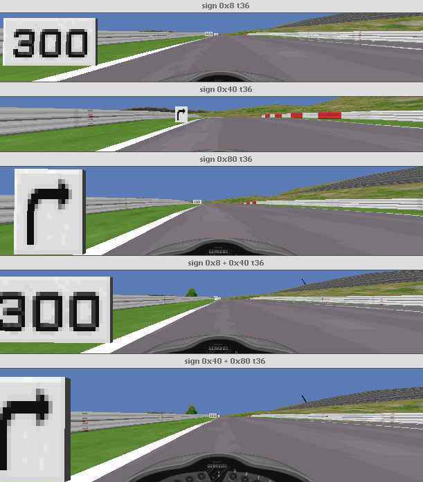
It was ando <gp2@ando.de>, who opened my eyes on this one.
There is also another way to get road signs: you can do it with objects. But there
you have to place them completely on your own, on the other hand you have full controll
about it.
More on objects later.
Overview
The third checkbox (0x4) in the Kerbs section is to select one of the two kerb definitions.
Unchecked you have 0xca (202) kerbs (type A), checked you have 0xcb (203) kerbs (type
B), no matter which ones are the low ones (this just depends on your definitions
in 0xca (202) and 0xcb (203)). To learn more about kerbs, have a look at the following
descriptions of the kerbs-commands by Nic "Swervin' Irvin'" Prins <n.prins@student.qut.edu.au>:
By Nic "Swervin' Irvin'" Prins <n.prins@student.qut.edu.au>
The two track-commands 0xca and 0xcb define the charcteristics of the two kerb types;
A and B. These two commands appear only once each in in every track. Once again,
for all tracks except F1ct16.dat, these are found in track section zero. For F1ct16,
they are found in track section 6. It actually doesn't matter where within the track
these are, but there's no need to move them anyway, so don't bother. If you place
a second 0xca or 0xcb kerb command somewhere into the track, this will basically
overwrite the existing command, such that kerb characteristics of this kerb type
for the entire track will come from the new command, not the existing one. My advice;
don't add, or move 0xca and 0xcb commands. You'll just confuse things.
Each of these commands has exactly the same arguments (variables), so we'll look
at them together. The five arguments are:
a1 : Unused (always set at zero)
a2 : Profile - the cross-section of the kerb. Affects, and is affected by, height
and width values.
a3 : Kerb Width.
a4 : Height at Track - How high the kerb will be at the track edge.
a5 : Height on Verge - How high the kerb will be at the edge fartherest from the
track.
We'll leave the Profile till last, as it is the hardest to explain, and your width
and two height values will change how this works, so we'll start with them.
a3 : Kerb width
This is simply how wide the kerb will be. possible values are from zero to 500+.
I say 500+ because I've never gone any wider than this and for existing (real) Formula
One circuits, this is about as wide as kerbs get. Interlagos, in Brazil, for example,
has very wide kerbs, which would be about 500. Just remember, that when you set a
very wide kerb, unless you adjust the CC-line (hard), or mess around with the track
widths(relatively easily, explained elsewhere in the tutorial), you, the human driver,
will be able to make full use of them, but the CCs won't, which will be in your favour,
obviously.
a4 : Height at track.
This value sets how high the kerb will be where the kerb meets the track. The idea
of the profile value (a2) is to move this height between the track edge and the far
edge, but more of that later. The possible range of values for this range from zero
to 32+. 32 is the highest value that you'll find in the original Microprose tracks.
Trust me, I don't think that you'll seriously want to make this any larger; 32 makes
a big enough kerb as it is.
a5 : Height on Verge
This value sets how high the kerb will be at the edge fartherest from the track.
It is in the same units as a4. Possible range of values are the same as for a4. Contrary
to what you might think, this value does not necessarily have to be the same as or
greater than a4. With clever usage of a2, the profile, you can do this and not get
a strange looking kerb.
a2 : Profile
This value remained unknown up to and including TrackEd 1.56. I discovered it a few
months back, but it was only now (as I was typing the Height at Track explanation,
in fact!) that I have an exact explanation for it. The function of this value, is
to define how far from the track edge the Height at Track (a4) will be. It sounds
funny, but trust me. The best way to look at this is in a two dimensional, x-y axis
system. In this system, Kerb Width (a3), and Profile, are x values. Both kerb heights,
therefore, are y values. The origin of this graph ((0,0) - where the x and y axis
meet), is the point where the edge of the track meets the kerb. We will consider
a kerb on the right hand side of the track. For a left hand kerb you would just mirror
the graph.
Let's say that the kerb width is 300, the Height at Track is 20, and the Height on
Verge is 30. Now when the Profile value is set to zero, the graph, which represents
the cross-section of the kerb, will look like this.
As you can see, from the origin, the kerb will rise vertically to a height of twenty.
From here, the top of the kerb will go to the point (300,30), which is the end of
our kerb. The line drawn from point (0,20) to point (300,30) is not a straight line.
GP2 will always give this line a small, positive curve. This means that this line
has a hump, or rise in it. This is just to smooth things out so to speak, and it
is not possible to alter this. Going back to the graph, you'll see that the kerb
created is undesirable. No kerb I have seen has such a large vertical edge to it
at the track edge.
Now let's do the same thing again, but using a Profile value of 20.
You'll notice here that the profile value has moved the Height at Track value 20
units to the right. The kerb now begins at the origin, then rises to the point (20,20).
Once again, this line is not perfectly straight. As before, the top of the kerb will
then go from this point to the verge edge, namely point (300, 30). As you can see,
we now have what you would consider a proper kerb.
You can probably work out for yourself that by making the Height on Verge larger
than the Height at Track, and using a good profile value, you can make a kerb which
rises from the track edge, and then falls away from the point (profile, height at
track) to the verge edge) and still have a 'normal' kerb, as I mentioned previously.
The Profile value is in the same units as Kerb width (Arg 3), and you can actually
make this larger than the width value. However, if you do this, you'll notice that
kerb is rather stupid looking, so doing this is not practical.
By Nic "Swervin' Irvin'" Prins <n.prins@student.qut.edu.au>
The two commands 0x8e and 0x8f are used to set the start position and the length
of a kerb on a track sector/s. 0x8e is used for kerbs that appear on the left hand
side of the track, and 0x8f for the right. These commands will only work properly
on type B (0xcb defined) kerbs. With a type A kerb, when you set one the kerb will
run for the entire length of the track sector. The only time when a type A kerb will
need one of these commands is in the rare instance when one of these kerbs will not
appear when you set one. For type B kerbs, how far the kerb will run along the track
sector can be changed by these commands, and it is far more common for these kerbs
to not appear when you set one, and these kerbs can be 'forced' as well.
These two commands have three arguments:
a1 : Unused
a2 : Offset; Start position in sector
a3 : Length
a2 : Start postion
When you place a 0x8e (left) or a 0x8f (right) command on a track sector with a type
B kerb, this value defines where the kerb will begin within the track sector, in
the units as track length. If type B kerbs are set in the following track sector,
on the same side, the kerb need not start in the track sector the 0x8e/f command
is set in.
a3 : Length
This is simply how long the kerb will run for from the start position. If you want
a kerb to be longer than the track sector, set type B kerbs for however many following
track sectors you want, and control the exact length using the command. This is good
as it means that you don't need to set one of these commands for each of the track
sector.
Forcing kerbs is done by the 0x8e and 0x8f commands. Quite often when you set a type
B kerb for a track sector, the kerb won't appear. What you will need to do is to
the find the closest track sectorbefore it, that will accept a type B kerb on the
same side of the track. It doesn't matter if you don't want to have a kerb appear
here, because it doesn't need to. Now make sure you have a type B kerb set in the
track section where you want it, and in the one before that will accept it. Now place
a 0x8e/f command in the sector that will accept the kerb. Take the distance >from
the start of this sector to the start of the track sector where you want the kerb.
Use this value as the Start Position value. Now you can make the kerb as long as
want, remembering that if you want to make it longer the track sector, to set kerbs
in the following track sector as well.
Forcing type A kerbs to appear is done in a similar way, but you can't control the
start or length of the kerb, and a kerb will appear in the preceding track sector
where you set the command, whether you like it or not. In this sense, as Martijn
Keizer so succintly put it, type B kerbs are intelligent kerbs, and type A kerbs
can be considered as stupid (his words!)
Some more track-geometry
Verge Width
by Nic "Swervin' Irvin'" Prins
The verge width is defined as the distance between the edge of the track and the
verge (ie. the fence) on each side. Verge width, combined with track width (see TRACK
WIDTH section), therefore determines the about of room perpendicular to the track
that the cars, be they CC's or human controlled, have to drive around in.
The values for verge width are found in the TRACK CHANGE DIALOG box. The two variables
are LEFT VERGE; the distance between the left hand edge of the track and the left
verge, and RIGHT VERGE; the distance between the right hand edge of the track and
the right verge. Small values will give you fences that are close to the edge of
the track (Monaco, for example, uses a value of 2 for each variable at most points
of the track). Larger values will move the fences further away from the edge of the
track (Useful for creating large runoff areas for sandtraps). The upper limit for
the verge width values is 255. Verge width, incidentally, is not measured in the
same units as track width. the verge width values that you enter define what the
width will be at the END of the track section. The width at the START of the track
section is the verge widths of the previous track section. The progression from one
verge width to another is linear. On a straight track section, going from a verge
width of 200 from the previous sector, to 100 for this sector, the fence be a straight
line from the start to end of sector; there is no fancy curved progression. Basically
this means that the gradient of the fence (left and right, not up and down) is constant.
The only section where the verge widths have no effect is the LAST track section.
From what I mentioned earlier, this should determine the verge width at the start
of the FIRST section. Instead, the left and right verge values can be found in the
track tree to the left. Open up the basic track directry, and then the TRACK CONFIG
directory. Here you will find two values called BEGIN LEFT VERGE and BEGIN RIGHT
VERGE. The values that you place in here will be the ones you wanted to place in
the LAST track section.
Verge width is always taken from the edge of the track to the verge, so that when
you change the track width, the fences will move closer together or futher apart,
but the distance from track edge to the corresponding verge will remain unchanged.
Also note, that when you change the verge widths, you may have to make some changes
to the object distances (see OBJECTS section, eventually...). The object distances
are taken from the centre of the track, so changing the verge widths can cause objects
to become too far away from the fence, or to be drawn within the fences.
Fence Height
The height of the fences are controlled by track- (or pit lane-) commands. For details
see the "Command Library" by the same author, commands 0x98 (152), 0x99
(153) and 0x9a (154). There you find a description of the mentioned commands by Nic
"Swervin' Irvin'" Prins.
Banking
From: "Martijn Keizer" <sa426090@sepa.tudelft.nl>
Well basically banking is the simpelest of adjustments one can make (that says something
about the rest...). Insert the command before the corner, insert the values and the
banking is done. After the corner, insert another banking command to get the track
straight again.
The first value is to define how long the transition is from zero to full banking.
The second is to define how much banking you want.
For the first corner on the SepaDelft track (get used to the name...) I used (15,1000)
as values. For the un-banking, the second value has to be 0, the first NOT zero,
because there will be a threshold otherwise. I used (15,0) as you can check easily.
Positive values give a banking with a higher left, negative values gives banking
with a higher right side. The banking seems to have a real effect on the grip of
the car, despite the fact that it is not a very much developed command. That is shown
in the fact that the CCars are drawn like they are riding on a flat surface. They
are no doubt uninfluenced in their grip level.
The track itself is the only surface that has an actual banking drawn. The grass
on the side and the armco are untouched. That means that if you go off and hit the
armco, the armco will be meters or feet underneath you. Therefore, banking should
be applied lightly and not too steep. Experiment if you don't believe it.
Textures are handeled by a few track- and pit lane commands.
0xc8 0xbb 0xbc.
How to deal with cmd 0xbc.
First there is my own try to describe it. Then you also find the version of Martijn
Keizer
With this cmd we do define an area, where a texture gets mapped. First we define
the size of the area, 2nd we select the texture and define how it gets mapped on
the definend area. We define repetition horizontal and vertical, rotation.
a1: offset
a2: location code. we select a ribbon.
the following values are valid:
4 (fence right); 5 (fence left); 8 (verge right); 9 (verge left); 10 (track); 11
(?ribbon1); 12 (?ribbon2); 13 (?ribbon3); 14 (?ribbon4); 18 (?ribbon5); 19 (?ribbon6)
a3: length of the mapping-area, follows the direction of the ribbon
a4: id of the texture out of a JAM-file.
a5: repetition of the texture side by side. (repetition horizontal)
a6: hard to describe. Maybe we can call it resolution of the placeholder in vertical
direction according to the texture. e.g. "HITACHI" mapped on a fence 3
times side by side (a5=3) in monaco, if a6=16. if p6=32 we have double the resolution
on the placeholder so there is space enough for TWO ROWS of 3 times "HITACHI".
p6=48 would be 3 rows, etc. in this example 16 is the half of the real vertical resolution
of the texture. I dont know if its ever half the resolution.
a7: vertical shift within the texture. If this shift is somewhat greater than 0 and
less than the vertical resolution of the texture, then the texture gets shifted upwards
by this amount. That means the upper margin gets cutted and pasted at the lower margin.
a8: rotation of the texture in steps of 90degrees.
value 0-15: 0 degrees
value 16-31: 90 degrees
value 32-47: 180 degrees
value 48-63: 270 degrees
From: "Martijn Keizer" <sa426090@sepa.tudelft.nl>:
About the 0xBC command
When applying a texture to a fence/ribbon/verge, it may be upside down, or wanted
upside down or turned. The code to do this is the arg8 - X angle, with codes 16,32,48
respectively, for 90-180-270 degrees rotation. (cost me some time to find out, typing
90 the first time, when you KNOW you are working with computercode, is quite stupid.
The Doom-editing I once did helped me remind that EVERYTHING goes in powers of two.)
The interface box on this command is pretty bad in 156, almost all changes are not
working. Instead, I use the properties box which is difficult because the textures
have no names, the places are just a number and so on. Not too difficult, but maybe
more of a hint to Paul Hoad. Seems like a little bug in the TE. Also, the nrows is
the number of rows of pixels on the bitmap that is mapped. Not the number of mapped
bitmaps that you want on your ribbon.
For example, for a regular advert, the number of pixels (nrows) is 16. On the other
hand, the nbitmaps command IS the number of times you want your bitmap placed on
the ribbon. For example, a fence with length 20 and only one nbitmap, give a very
stretched-out advert on the fence. I use an average of 1 advert per 4-5 units of
length, which looks OK to me. Beware of the short adverts (like Castrol) because
they will be very streched out.
Overview
Some of you already have noticed, cc-line editing is a story by its own. There is a tutorial of the same author on this subject on its way to its public. Its still pretty raw, thats why its not yet published but the "brief introduction to cc-line editing" is available directly from the author.
TE: track editor.
cmd: command. commands are included in track- or pitlane-sectors. They can be accessed
in the track-tree.
t99 or t99(99): track sector 99, its length in brackets.
p99 or p99(99): pitlane sector 99, its length in brackets.
c99 or c99(99): cc-line sector 99, its length in brackets.
s/f-line: start/finish-line, thats where the end of our track meets the beginnig
again, thats where the circle closes, and where time counting starts/ends.
(?): Because english is not my first language, and because my english dictionary
is not that good, sometimes I am not absolutely sure about a used term. In that case
i either add the german term and you may use your german dicionary. Or if I am a
bit more sure, but not absolutely sure, I add a question mark in brackets. However,
that means: I am sure about the fact, but not sure about the term. If I'm not sure
about the fact, I say so, or the fact is not mentioned at all.
Overview
version 2.1
-remove download facility, because there is now a general download facility at the
tutorial page
-exchanged t_geom.jpg sketch, because "end angle" was drawn wrong
-slight revisions of the text here and there (main point: working in the track-tree
with open track-data-table seems to rise the probability of a crash of the TE)
version 2.0
-complete rework of the first part in order to make it more look like a guide
-the tutorial is now based on TE 1.6
-adapted to unified terminology
-slight change in chapter "Verge Width" by Nic "Swervin' Irvin'"
Prins. the maximum width IS 255.
version 1.1
-the tutorial is now based on TE 1.5.7
-new chapter "Verge Width" by Nic "Swervin' Irvin'" Prins
-new chapter "Banking" by Martijn Keizer
-chapter about cmd 0xbc (texture mapping) two versions Martijn Keizer and addie
-chapter track-geometry extended
-chapter cc-line editing extended by explanations on the cc-line-editor-dialogbox.
-added picture with ramp (ramp.jpg)
version 1
starting things off. first version mainly on the track-change-dialog-box of TE 1.5.6,
track geometry basics and track-sector features. plus introduction to cc-line editing.
Remember: the track works how you PROGRAM it, and not how you want it !